Pump support structure
For a team project in Mechanical Analysis for Design, we developed a support structure for a pump-and-pulley assembly. The work connected structural analysis and material selection with component drawings and a physical prototype. The Group 28 assessment records a 117 lb applied load and 3.81 mm platform-end deflection.
- Problem
- Hold a pump and pulley on a platform at the position set by the test setup, carrying the applied load back into the mounting structure, with limits on deflection, height and budget and a score for low mass.
- My contribution
- With my two teammates, I worked on the load-path analysis, the stress and factor-of-safety derivations, material selection, the bill of materials, the prototype build and the load test. I also completed the separate material-selection assignment shown below.
- Engineering decisions
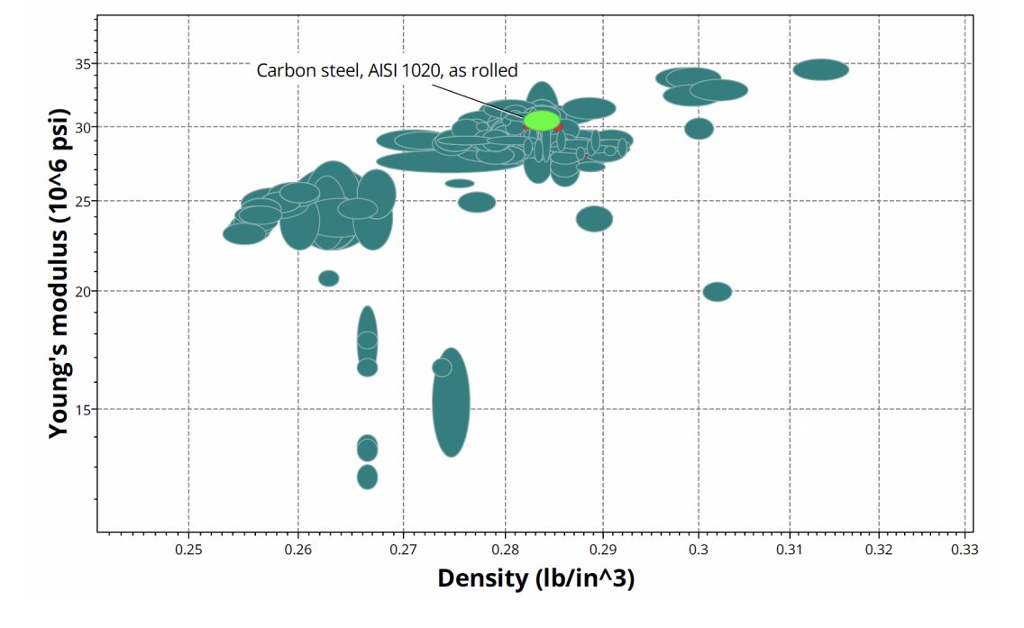
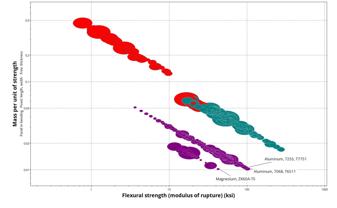
- We moved from a preliminary steel platform and arms to 6061 aluminum, for its strength, corrosion resistance, machinability and low density. We chose stainless steel for the pins, which needed more than 300 MPa yield.
- Evidence
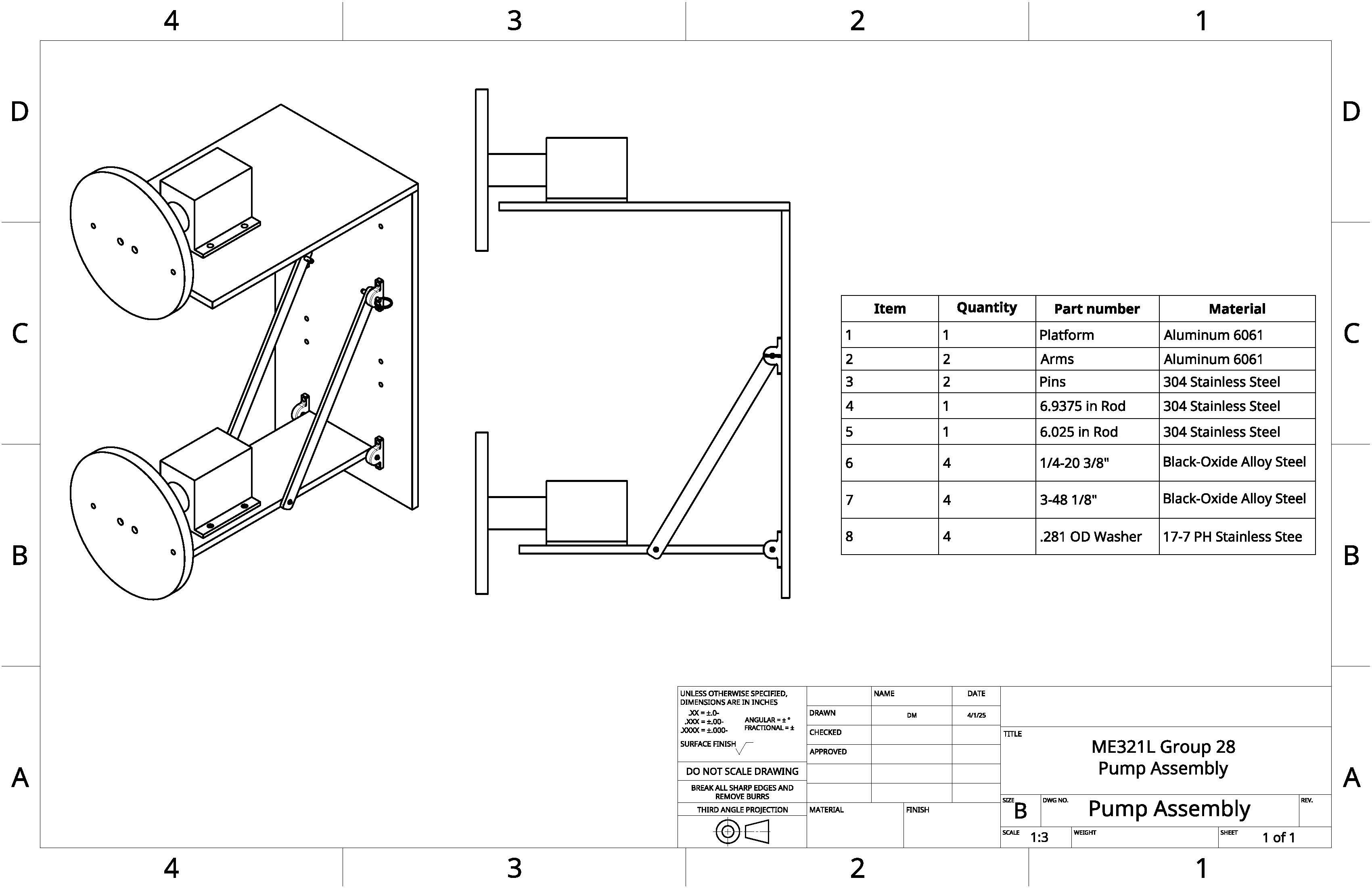
- The assembly drawing and bill of materials, a component drawing, free-body and moment diagrams, a material-selection chart and the recorded prototype sheet.
- Outcome
- The prototype attached to the test setup and was recorded at a 117.0 lb applied load, with 0.15 in (3.81 mm) of deflection at the platform end.
- Scope
- These are single recorded team results. 117 lb is the load applied in the assessment, not a certified rating or a failure load. Our report set a 1 mm deflection limit, so the prototype didn't meet every target.
- 117.0 lb
- Applied load recorded on the team's prototype sheet. Not a rating or a failure load.
- 3.81 mm
- Platform-end deflection recorded at that load (0.15 in).
- 5 lb 8.2 oz
- Recorded mass of all prototype components.
My work on the project
We shared the work across the team of three. My part included:
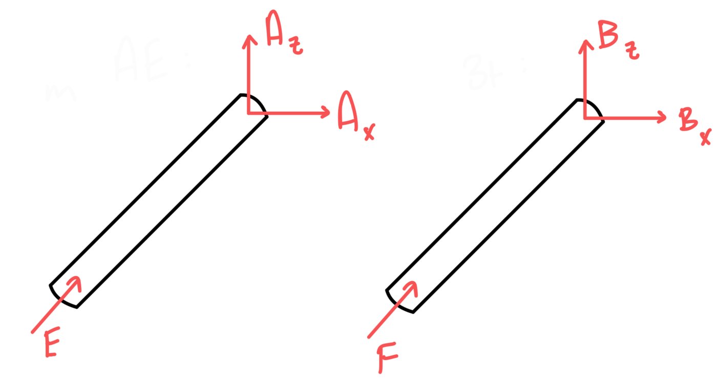
- Drew free-body diagrams of the platform, arms and pins, and followed the load through each joint.
- Derived the bending, axial, torsion, shear and pin-loading stresses, and the factor-of-safety and buckling expressions.
- Estimated stress concentration factors at the pin holes.
- Set material requirements and screened candidates with material-selection charts.
- Helped put together the bill of materials against the $150 budget.
- Helped build the prototype, mount it on the test setup, and run and record the load test.
Load path
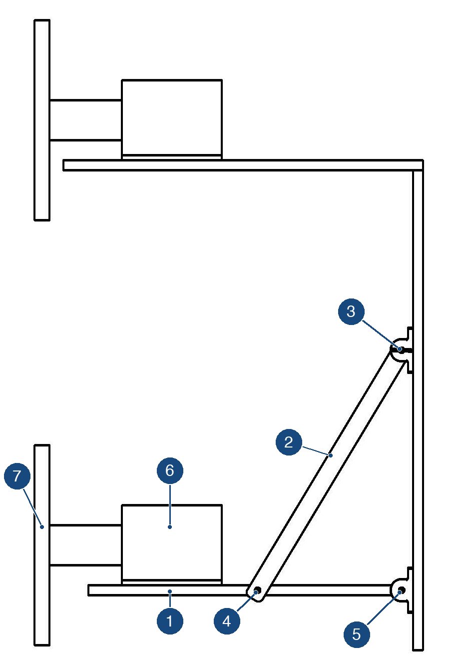
- 1: Platform. Carries the pump and pulley and is pinned to the mount at its back edge.
- 2: Arm. One of two, in compression between the platform and the mount.
- 3: Arm-to-mount pin. In direct shear.
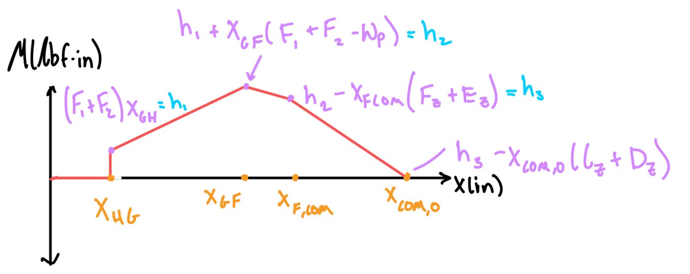
- 4: Arm-to-platform pin. In direct shear. The report expects the largest platform moment at this section.
- 5: Platform-to-mount pin. In direct shear.
- 6: Pump. Sits over the platform's four tapped holes.
- 7: Pulley. The assessment loads the structure through the pump and pulley, and the report sets the platform length so the pulleys stay aligned.
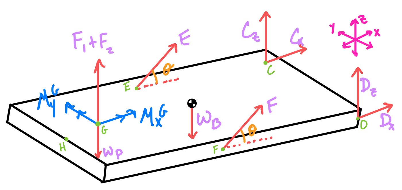
The pump load and weight act near the platform's free end. The platform bends between that load, the arm pins and the pinned back edge, which also puts it in torsion, transverse shear and tension from the arms. The arms act as two-force members in compression, and the pins carry direct shear. The team expected arm BF to carry more than arm AE, and the highest platform stress near the pin holes.
From the free-body diagrams to the stress checks
The team's report turns each component's load into a stress and a factor of safety. These are the symbolic forms, with Kt the stress concentration factor at the pin holes:
Platform: σmax = Kt 6Fl / (W t2), δmax = 4FL3 / (W t3 E)
Arm: σmax = Kt F / (w0 t), Pcr = π2E w0 t3 / (12 L2)
Pin: τmax = Kt 4F / (π d2)
Ductile materials were checked with maximum shear stress and brittle ones with Coulomb-Mohr. At the preliminary dimensions, the report estimates Kt of about 3 for the platform, 2.6 for the arms and 2.0 for the pins. The deflection expression treats the platform as a cantilever, a simplification of the pinned and braced structure.
Material selection
The report set requirements before choosing: at least 200 MPa yield and 70 GPa modulus for the platform and arms, more than 300 MPa yield for the pins, corrosion tolerance for freshwater exposure, machinability, and a $150 total budget.
| Part | Preliminary | Documented assembly selection |
|---|---|---|
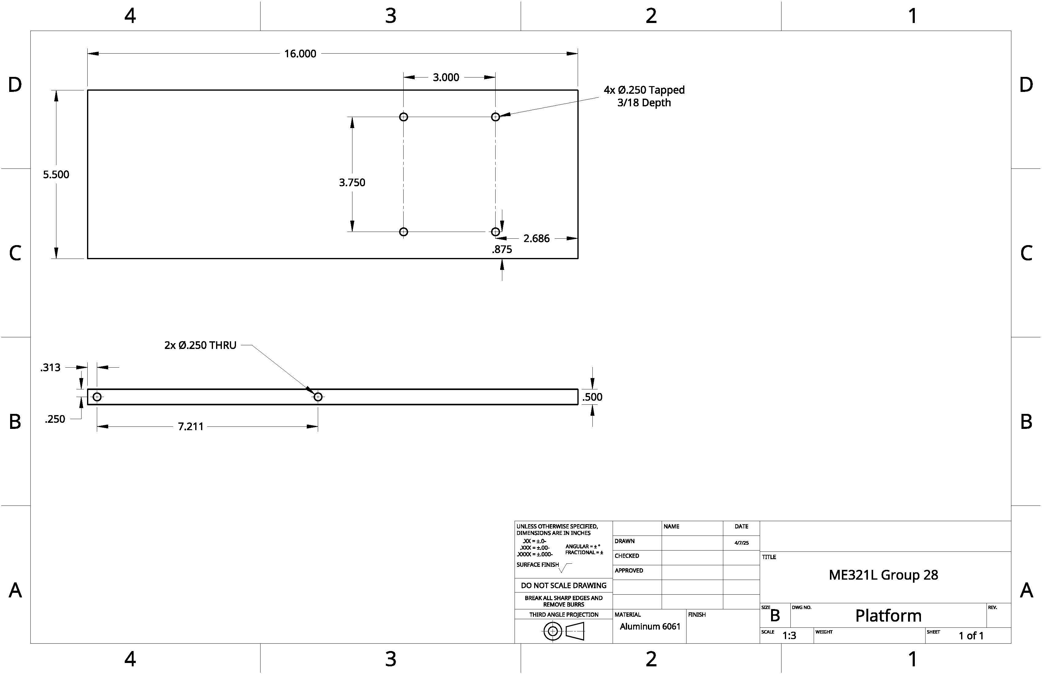
| Platform | Steel plate, 12 × 18 × 0.5 in | 6061 aluminum, 16 × 5.5 × 0.5 in |
| Arms | Steel bar, 15 × 1 × 0.25 in | 6061 aluminum, 15 × 0.9 × 0.25 in |
| Pins and rods | 3/8 in diameter pins | 304 stainless steel; the drawn holes are Ø0.250 in |
Drawing
Recorded prototype results
| Quantity | Recorded result |
|---|---|
| Applied load | 117.0 lb |
| Platform-end deflection | 0.15 in / 3.81 mm |
| Prototype mass | 5 lb 8.2 oz |
| Assembled height | 13 in |
| Attachment to test setup | Successful |
The procedure raises the load in increments toward the project's specified maximum, then measures the deflection at the platform end. The sheet records one set of values. It doesn't record a failure load, repeated runs or fatigue behavior.
Our analysis report set a 1 mm limit for deflection at the platform's end, and the assessment gave full marks for 0 to 3 mm and the next band for 3.01 to 6 mm. The recorded 3.81 mm is above both, so the prototype carried the load but didn't meet the stiffness target.
Team
Group 28, with Dylan Matian and Miles Bradley.
Source files
- Pump support: recorded prototype sheet
One page with the team's recorded mass, height, attachment, load and deflection.
- Pump support: material selection excerpt
Four pages from the team's analysis report, with the requirements, charts and purchasing list.
- Material selection: individual assignment
My five-page ME 321L assignment, deriving performance indices and using Ashby charts for two applications.