Bolted pressure vessel
For the machine shop project in Mechanical Design, my team designed and machined a two-piece aluminum pressure vessel, bolted together at a central flange and sealed with an O-ring. The dimensions on this page come from our preliminary design proposal, not from measuring the finished part.
- Problem
- Contain a 5.27 MPa internal design pressure in a two-piece machined vessel, with a sealed, bolted joint.
- My contribution
- I did the calculations for the vessel dimensions, the O-ring and the bolts, and I took part in the machining.
- Engineering decisions
- We increased the calculated 2.65 mm wall to 5 mm so the part would be easier to machine. The O-ring sits in a face gland in the flange, clamped by six class 4.8 M4 bolts, chosen over class 9.8 for cost.
- Evidence
- The CAD assembly and drawing, the proposal's sizing calculations and a thick-cylinder check of the selected wall.
- Outcome
- The machined vessel completed the classroom test without an observed failure.
- Scope
- The test result is qualitative, because the test pressure, medium and duration weren't recorded. The joint calculations are preliminary and don't establish a joint safety factor.
- 5.27 MPa
- Internal design pressure, from the project specification.
- Design target: factor of safety 2 against yielding
- Used to size the wall. It is a target, not a verified final factor of safety.
- 25 mm bore, 5 mm wall
- Proposal dimensions, not as-built measurements.
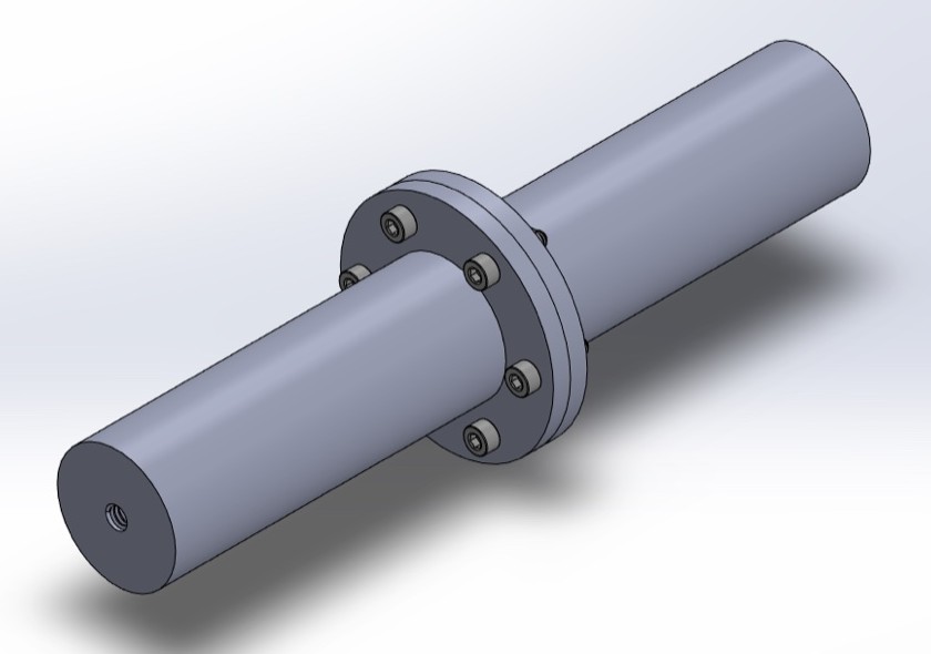
Design record
| Type | Record | How to read it |
|---|---|---|
| Pressure specification | 5.274 MPa internal, 0.101 MPa external | Given in the proposal's dimension table. Its joint calculation uses a 5.171 MPa pressure difference. |
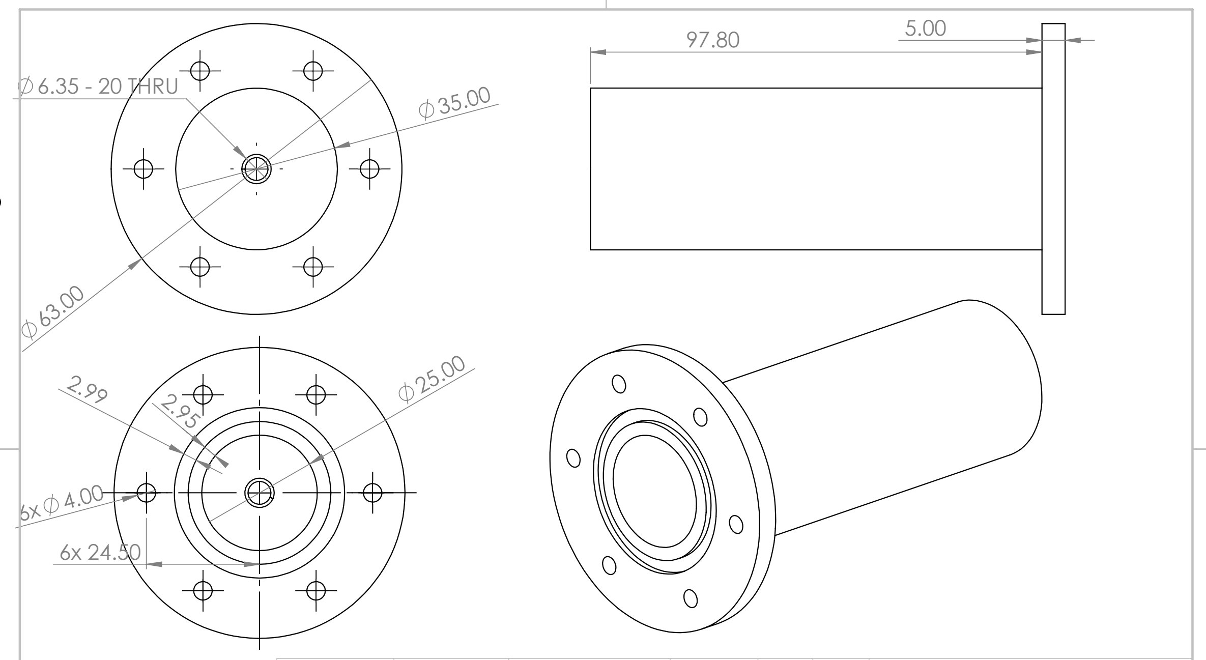
| Proposal dimensions | Ø25 mm bore, Ø35 mm tube, Ø63 × 5 mm flange, six Ø4 mm holes | From the proposal drawing. These aren't as-built measurements. |
| Analytical calculation | 18.6 MPa von Mises at the bore; 2,450 N preload target; 2 N·m torque estimate | Predictions from hand calculations. None was measured on the part. |
| Classroom test | Completed without an observed failure | Qualitative. The test pressure, medium, duration and leak rate weren't recorded. |
Wall sizing
We chose 6061 aluminum for its cost, machinability and strength, with a 25 mm inner diameter. The proposal's first estimate called for about 2.65 mm of wall, and we increased that to 5 mm, which makes the part easier to machine and gives a 35 mm outer diameter. A thick-cylinder check of the 5 mm wall gives 18.6 MPa von Mises at the bore, against the proposal's 55 MPa yield strength.
Where the 2.65 mm estimate came from
The proposal set a thin-wall hoop stress expression equal to Sy/n, with Sy = 55 MPa and n = 2:
t = Pi n di / (2 Sy − n Pi) ≈ 2.65 mm
That gives t/ri ≈ 0.21, which is outside the usual thin-wall range of about 0.1, so it is only a first estimate. It also checks hoop stress alone. A Lamé calculation of hoop stress gives nearly the same wall, about 2.68 mm, but a maximum-shear calculation at the same target needs about 3.4 mm.
Thick-cylinder check of the 5 mm wall
At t/ri = 0.4, the selected wall needs a thick-cylinder treatment. These are Lamé stresses at the bore, where they are highest, for ri = 12.5 mm, ro = 17.5 mm and 5.27 MPa of internal gauge pressure:
σθ = p (ro2 + ri2) / (ro2 − ri2), σr = −p, σl = p ri2 / (ro2 − ri2)
| Analytical prediction | Stress at bore | Margin against 55 MPa |
|---|---|---|
| Hoop, σθ | 16.3 MPa | |
| Radial, σr | −5.3 MPa | |
| Longitudinal, closed ends, σl | 5.5 MPa | |
| Von Mises equivalent | 18.6 MPa | 2.95 |
| Maximum shear (σθ − σr) | 21.5 MPa | 2.56 |
Both margins clear the design target, but they are not a final factor of safety for the vessel:
- Location. They cover the straight cylinder wall, away from the flange, end cap and threaded port.
- Material. 55 MPa is the proposal's yield strength. That value is typical of annealed 6061-O, while 6061-T6 is about 276 MPa. The temper of the stock we machined wasn't recorded.
- Pressure. The calculation treats 5.27 MPa as gauge. If the specification meant absolute pressure, the stresses would be about 2% lower.
Face seal
The 38 mm O-ring outer diameter is larger than the 35 mm tube, so the O-ring sits in a gland cut into the flange face. When the bolts close the two faces, the 4 mm cross-section is squeezed into a 3 mm deep gland, which is 25% compression. The gland is sized so the uncompressed O-ring fills about 70% of its cross-section, leaving room for the rubber to deform.
Choosing the seal material and gland
We compared silicone, fluoroelastomer, thermoplastic polyurethane and nitrile, and chose nitrile (Buna-N) for its abrasion resistance, strength, temperature range and resistance to gas permeation. The proposal selects a 30 mm inner diameter O-ring with a 4 mm cross section.
The gland follows from three targets: a gland about 3% larger than the O-ring's inner diameter, 25% compression, and about 70% fill. That gives a 30.9 mm gland inner diameter, 3 mm depth and 5.99 mm width.
Bolted joint
Pressure inside the vessel pushes the two halves apart. The bolts are tightened first, so the flange faces are already clamped together before that load arrives. Each bolt and the flange it clamps then share the separating load in proportion to their stiffness: the bolt takes the fraction C, and the rest goes to relieving the clamp.
Fbolt = Fi + C P, Fclamp = Fi − (1 − C) P, C = kb / (kb + km)
So a stiffer flange means less added bolt load, and more preload means more clamp to lose before the joint opens. The proposal selects six M4 × 0.7 bolts, 16 mm long, in property class 4.8. Preloading to 90% of proof load gives about 2,450 N per bolt and about 2 N·m of torque, using At = 8.78 mm², Sp = 310 MPa and k = 0.2.
The preliminary proposal includes preload, stiffness and joint-constant calculations, but they were never reconciled with the final geometry, flange material and installed hardware. So I don't state a joint safety factor here.
Reconciling the preliminary proposal
I rechecked the proposal's arithmetic against its stated inputs, and it holds, apart from rounding the preload up to 2,500 N. The open items are in the inputs and between the proposal's early draft and its later version, both dated October 16, 2025.
| Item | What the records show | Status |
|---|---|---|
| Fastener count | The early draft says four in one description and six in the selection. The later version and drawing show six. | Six in the proposal |
| Member modulus | The member stiffness uses 207 GPa, a steel value, for aluminum flanges. With about 69 GPa, C rises from 0.144 to about 0.335. | Correction needed |
| Pressure convention | 5.274 MPa internal and 0.101 MPa external would give a 5.173 MPa difference. The joint calculation uses 5.171 MPa. My Lamé check uses 5.27 MPa as gauge. | Under 2% effect |
| Pressure area | The separating force uses the 25 mm bore. Pressure can reach the O-ring, which sits at a larger diameter. | Correction needed |
| Length and volume | L = 195.6 mm matches two 97.8 mm halves, but a 25 mm bore over that length holds about 96 cm³, not the listed 60 cm³. The listed L/D of 4.89 with a 25 mm bore gives 122 mm and 60 cm³. | Inconsistent in the proposal |
| Bolt circle | The text uses 42 mm. The drawing's 24.5 mm hole position gives 49 mm, where six bolts fall just outside the proposal's 3 to 6 spacing rule (6.4). | Inconsistent in the proposal |
| Gland width | The calculation gives 5.99 mm. The drawing shows 2.99 mm, which is narrower than the 4 mm O-ring. | Machined width not recorded |
| Equation references | The early draft has “FILL” placeholders. The later version replaces them with a reference to its derivations. | Resolved in the later version |
This check shows how much those inputs matter. It uses the 2,450 N preload target and 5.171 MPa, against a 2,722 N proof load. It isn't a rating of the vessel, and the installed preload isn't known.
| Assumption | Load per bolt, P | C | Bolt load | Clamp left |
|---|---|---|---|---|
| Proposal: bore area, 207 GPa | 423 N | 0.144 | 2,510 N | 2,087 N |
| Bore area, aluminum flanges | 423 N | 0.335 | 2,591 N | 2,168 N |
| O-ring centerline (Ø34 mm), aluminum | 782 N | 0.335 | 2,712 N | 1,929 N |
| Calculated gland OD (Ø42.9 mm), aluminum | 1,244 N | 0.335 | 2,866 N | 1,622 N |
The clamp stays positive in every case, so the faces stay together on paper. The last case goes past the bolt's proof load, so a joint safety factor depends on the final geometry and installed preload, which weren't recorded.
Machining and test
After the design work, we machined the vessel in the shop. The machined vessel completed the classroom test without an observed failure. This is a qualitative outcome. The test pressure, medium, duration and leak rate weren't recorded, so it doesn't show that the vessel was tested at its design pressure.
Team
This was a team of three, with Sophia Singer and Andrew Tucker.